
Motherboard IDE Ports
Depending on the manufacturer, the first IDE connector on the motherboard is identified by one of the following terms...
-
IDE0
-
Primary
-
Master
Depending on the manufacturer, the second IDE connector on the motherboard is identified by one of the following terms...
-
IDE1
-
Secondary
-
Slave
Majority of motherboards have two IDE ports. One labeled as IDE0 or Master and One labeled as secondary or IDE1
The motherboard also has one port for the floppy drive. This port is not an IDE port but people mistake it for an IDE port. This cable is skinnier than the other two cables. The two IDE cables are the same size in width.
IDE0 on the motherboard is for the hard drive connected on the ID0 or primary IDE cable connector. You can hook a second hard drive or zip drive to IDE1 or Secondary on the IDE cable. You can connect a CD-ROM there if you want but not recommended.
On the motherboard, the connector closest to the edge of the motherboard is usually the IDE0 or primary connector. I believe all motherboards are setup that way but since there is so many different manufacturers, there can be one out there that is different.
The connector behind it is either the floppy drive or the IDE1 secondary connector. Each motherboard is laid out different. the floppy connector will be smaller than the other two.
For troubleshooting, you can connect IDE0 cable on the IDE1 motherboard connector and the IDE1 cable on the IDE0 motherboard connector.
The master drive will be connected on the end of the cable. It is listed as either IDE0 or as Master. The drive in the middle of the ribbon cable is listed as secondary, slave or ID1. Another words, Your C Drive will be on Primary connector on the IDE cable and will be connected to IDE0 on the motherboard.
You usually connect tape drives and CD-ROM's to IDE1 on the motherboard. When you connect the cables they will only connect on the motherboard one way. There is a notch on the IDE cable and there is a slit on the motherboard connector. Just line up the two connectors. (The red line on the ribbon cable indicates pin 1 on the cable) The Pin 1 will face the power connector on the IDE device.
Drawings below are not drawn to scale
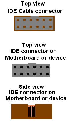 |
The connector on the IDE device is set up the exact same way as the connector on the motherboard. It will on connect one way (unless you force it and then it will not work)